Mini Marcos Owners ClubMini Marcos Mk. III Build Sheet (circa 1969)As supplied with Ray Rawlinson's Mk. III, LUR98H. Kindly scanned and OCRed by Paul Harcourt. DOORS (STAGE 1)Place two ¼" packings on the bottom edge of the door aperture and secure in place with masking tape. Place door in position, resting on the packings and ensure that there is an equal gap at the front and rear edge. Offer up hinges to the door and mark the securing bolt hole positions. (The moulding of the front door pillar shows the correct hinge heights). Remove the door, drill hinge holes and secure the hinges to the door. Offer up door to body, mark out the hinge holes in front door pillar and then secure hinges. Remove packing pieces and check door for clearance. If necessary, adjust position of door by elongating hinge holes in the door pillar. The door may be twisted so that when closed the rear edge does not lay flush with the rear door pillar; this does not matter and will be adjusted at a later stage of assembly. DOOR WINDOWS (STAGE 1)Remove the four screws from the window fram (at front and rear of quarter lights). Offer up the window to the door to ensure correct fitting. If necessary file out the grooves in the door for the window frame. Apply sealing compound to the bottom edge of quarter light frames and place window into door. Drill door 5/32" through holes left by the removal of the four screws, also through the holes at the front and rear edge of the frame. Screw No. 8 Self Tapping Screws through holes and secure with spire nuts. Drill two holes through the bottom runner and screw the runner to the two wooden blocks bonded to the bottom of the door. Grease the runner to ensure smooth action of the window stay. Fit the window locks with the Self Tapping Screws supplied. DOOR LOCKS (STAGE 1)Using the escutcheon plate as a template mark and drill to accept escutcheon plat and door handle. Place door lock into moulded recess and drill the three securing screw holes (5/32"), screw lock to door using No. 8 Self Tappers and Spire Nuts. Fit handle and escutcheon plate. It may be found necessary to extend the handle shaft to allow the fitting of the internal pull cord. This is done by removing securing pin (shaft to handle), withdrawing shaft from handle to correct length, re-drilling 3/32" and replacing pin. Fit and secure pull cord to shaft judging correct tension of cord. Mark and drill frontsecuring hole but DO NOT secure cord to door. DOOR PANELS (STAGES 1 and 2)
Thread the internal pull cord through panel, secure the point previously drilled and refit the door trims. DOOR CATCHES (STAGES 1 AND 2)Close door and mark position of catch plate. Offer catch plate to body, drill holes (slightly elongated) and secure catch plate, adjust as necessary. WINDSCREEN (STAGE 1)The windscreen is easily cracked and therefore great care must be taken in its fitting. The ideal tool for this operation is a blunt screwdriver with all corners rounded; this helps to prevent cutting the rubber and chipping the edge of the screen. Trim the windscreen aperture with a large file, until the large diameter rubber fits into its recess. Fit rubber around aperture, starting at the centre of the off-side door pillar. Ensure that the rubber is pushed firmly into the corners. Cut the rubber ¾" too long and force into position. Insert the bottom edge of the screen into the rubber surround. Slowly work the screen completely into the surround (using the screwdriver) firstly on the off-side, then the near-side and finally the top edge. The Claytonrite filler strip (chrome strip) is then fitted. This must be done with a special Claytonrite tool. The join in the filler strip should be opposite the join in the rubber. A 1" overlap should be left when the strip is fitted to allow for any shrinkage. A day is an ample length of time for shrinkage to take place when the strip must be cut to the right length and the end tucked in with a screwdriver. REAR WINDOWS AND QUARTER LIGHTS (STAGE 1)Exactly the same procedure is used for the fitting of the rear and quarter light glasses, the only differences being:-
DOOR SEALS (STAGE 1)The door seals are fitted to the flange around the door apertures. If normal Mini seals are used, it is essential that a contact adhesive is used to hold them in position. However, we supply a seal which is self-clamping to the flange and is coloured on the internal section, giving a far neater appearance. BONNET (STAGE 1)Place bonnet in position and if necessary trim the bottom edge until bonnet fits flush. Remove the bonnet and drill one 5/16" hole through the centre of each wooden block at the front corners. Refit bonnet and mark the body through the hinge holes. Drill these holes and insert hinge through bonnet into body. Screw bonnet locks (obtainable from us) into ready drilled holes; bend locking tongue to the correct angle to ensure the bonnet is firmly held when locked. NOSE PIECE (STAGE 1)Offer the nose piece to the body and trim edges if necessary. Secure with three self-tapping screws and spire nuts, 1" back from front edge. Finally secure with one screw through each of the internal flanges at the rear of the nose. MECHANICAL : ALL STAGESThis is purely a sequence in which to assemble the mechanical components of the Mini Marcos. All details of adjustments and alterations required for assembly are given and any other details may be acquired from the makers manual. All pipes, clips etc. that are necessary for the conversion are obtainable from the factory in an Assembly Kit (£7.10.0). FUEL TANKA Mini van fuel tank must be fitted in the Mini Marcos; before installing the tank cut off the filler pipe 2" from the base. Apply a sealing compound around the tank aperture and place the tank into position from inside the car. Drill ¼" holes in the floor to line up with the holes in the flange and secure the tank. Place the original grommet into the filler pipe hole in the body and insert the top half of the filler pipe. Connect this to the tank with 2" internal diameter hose and hose clips (Assembly Kit). A Mini van fuel gauge sender unit must then also be fitted. REAR LIGHTSWe recommend the use of the van type rear lights turned upside down. Secure at pre-drilled positions. Mark the centre point between the lights at a point above number plate position and secure the number plate illuminating light. REAR LOOMIt is easiest to use a van rear loom. If necessary a car loom can be used, but the wires will have to be extended at the rear end. (Extra wire provided in Assembly Kit). The loom runs from right to left across the back of the car, along the left hand side (tucked well into the corner) through the bottom hole in the front torsion box and out of the top hole behind the dashboard. The loom is secured by P clips and pop rivets (provided in the Assembly Kit). Each rear light must be earthed through a securing screw to the common earth in the loom as there can be no earth through the glass-fibre body. HEAD AND FRONT INDICATOR LIGHTSThese lights are fitted and adjusted in exactly the same way as on a Mini variant. FRONT LOOM, CONTROL BOX, FUSE BOX AND FLASHER UNITThe front loom runs from behind the dashboard, through the hole at the right of the bulk-head along the right side of the engine compartment and along the front valance from right to left; it is secured by P clips and pop-rivets. It is essential when positioning the loom to leave enough spare wire behind the dashboard to allow it to be removed for any repairs, etc. The control box, fuse box and flasher unit are all secured to the side of the engine compartment in as high a position as possible. (The loom controlling their actual positions). Connect up the front and rear looms and front lights. HORNThe horn is secured on the edge of the access hole in the nose under the nose piece. Once again the feed wires control the position. PEDAL ASSEMBLY AND MASTER CYLINDERSThe pedal assembly is secured in the normal manner through the beam and under the dashboard. Ensure that the correct cylinders (clutch and brake) are attached to the respective pedals; The throttle pedal is secured by two bolts through holes drilled in the bulkhead. The throttle cable is secured through the bulkhead. Make certain when drilling the hole for the throttle cable guide that it is at the same height as the top of the pedal linkage. BRAKE PIPESMount the 'T' connection on the bulkhead, the cross beam besides the clutch pipe bracket and in line with the brake master cylinder. Do not fit the pipe - ('T' connection - front suspension) - until after the sub-frame is fitted. The brake pipe runs from the 'T' connection down the bulkhead, between the steering rack mountings and along the offside of the tunnel. It must be tucked well into the top corner and secured with P clips (provided in the Assembly Kit). CLUTCH PIPEThe clutch pipe runs straight from the master cylinder to the bracket on the beam in the usual manner. FUEL PIPEThis must be straightened before fitting. Mount the pipe on the front bulkhead (ready to be connected to the flexible carb feed), between the steering rack mountings and then along the tunnel. It must be tucked well up into the top left hand corner to ensure there is no fouling of exhaust or gear leaver extension. Leave enough pipe at the rear to connect to the flexible outlet from the fuel pump. WIPER MOTOR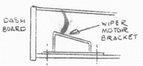
The wiper motor is mounted on its special bracket behind the dash. The operating cable and wheel boxes must be fitted first to the pre-drilled positions and the cable then controls the position of the mounting bracket. SCREEN WASHERThe screen washer is mounted on the near side of the engine compartment well back towards the bulkhead to avoid fouling the radiator. The nozzles are mounted in the pre-drilled holed beside the wiper arm mountings. The operating pump is mounted in the dashboard and can be left until the dashboard is built up. HEATERThe heater is mounted in a central position as far forward and as high as possible under the dash. If a fresh air heater is fitted, the fresh air hose must be mounted from the front valance, along the right hand of the engine compartment, through the bulkhead and to the heater. Extra holes will have to be made through the bulkhead and through the bottom of the dash valance. The demisters are then screwed to the pre-drilled positions and connected to the heater by the flexible pipes. MAIN FEEDThe main feed runs from the battery to the solenoid on the starter. It will be necessary to extend the cable (Assembly Kit). This cable runs from the battery box along the off-side of the car (well into the corner), through the torsion box and along the off-side of the engine compartment. STEERING RACK AND COLUMN
PREPARATION AND INSTALLATION OF REAR SUB-FRAMEFUEL PUMPRemove fuel pump from mounting bracket and replace when sub-frame is mounted into body. LOWERING SUSPENSIONLowering of the suspension is carried out by shortening the suspension trumpets. Take the pressure off the suspension and remove the trumpets. Shorten the trumpets by 1/5" at the narrow end and replace. HAND BRAKE CABLESIt is necessary to fit shorter hand brake cables (Assembly Kit). This is done in the usual manner. SUB-FRAME
SHOCK ABSORBERSThe rear shock absorbers are mounted through the holes in the top of the wheel arches and secured in the usual manner. FUEL PUMP AND BRAKE PIPESConnect the brake pipe ('T' connection rear sub-frame) to the restrictor valve on the sub-frame. Refit the fuel pump to the bottom of the mounting bracket and connect the pump to tank with flexible hose and van outlet pipe (Assembly Kit); connect the pump to the carbs pipe with flexible hose. PREPARATION AND INSTALLATION OF FRONT SUB-FRAMELOWERING SUSPENSIONWith the special B.M.C. tool or a long bolt and tube (compress the front suspension rubbers). Remove the suspension trumpets and shorten them 7/16" at the narrow end; refit the trumpets and release the rubbers. LOWERING THE RADIATORIt is necessary to lower the radiator ¾" to fit the Mini Marcos. Remove the radiator and cowl from the sub-frame. Remove the cowl by unscrewing the 6 securing screws. Mark and drill the 6 holes in the cowl ¾" lower. The corner of the cowl must now be removed to allow the radiator header tank to fit. Refit the cowl to the radiator and refit the assembly into the sub-frame. SPEEDO CABLERemove the standard cable and fit a special longer cable (Assembly Kit). SUB-FRAME (INSTALLING)With the front sub-frame complete, wheels on and standing upright, lift the front of the body over the assembly and lower. (This is easily done by two people lifting the front and the car rolling on the rear wheels). Secure with the four studs through the beam and two front securing bolts. Connect all electrical connections, brake and clutch pipes. Jack up front of the car and secure the four rear securing bolts. Whilst doing this, secure the front to rear sub-frame earth cable (Assembly Kit) to one of the bolts. Run the cable along the underside of the car to the rear sub-frame and secure this by drilling and bolting to the sub-frame. SHOCK ABSORBERSThe shock absorber top mounting bracket holes will require cleaning with a ¾" drill; bolt brackets to body and fit shock absorbers. STEERINGConnect the track rods up to the steering arms; it is necessary to adjust the toe-in when the car is completely built. HAND BRAKEThe hand brake lever is bolted to the bracket that is bonded to the top of the tunnel. BATTERY EARTHThe battery earth lead runs from the battery, through the floor and is bolted to the rear sub-frame. Do not secure this to any sub-frame mounting bolts - the mounting blocks are rubber mounted and therefore insulated. Fit the earth wire from the fuel tank to the battery earth. DASHBOARDThe dashboard should be built up fully before fitting. All necessary holes pre-drilled to take switches, cables and instruments. Hold dashboard in position, connect up to the loom and secure with the three screws supplied. When the bonnet is finally fitted, make sure you secure hinges to wooden blocks by wood screws. HYDROLASTIC SUSPENSIONWhere hydrolastic suspension is used, it is necessary to straighten the fluid pipes - these are fitted to the underside of the car and run from the mounting brackets on the beam to the rear member of the rear sub-frame. It will be necessary to make 2 right-angle brackets to mount the pipes to the sub-frame. These should be made of 1/8" metal, 1" wide and each of the sides 1 1/2" . These pipes must befitted after the rear sub-frame and before the fitting of the front. |
 It is during this operation that the
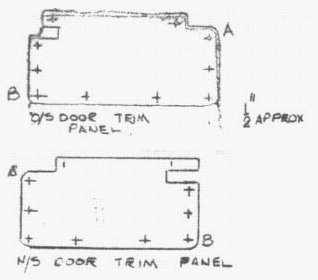
adjustment to twist the door is carried out. The panel is secured by 10 x No. 8
Self Tapping Screws and Spire Nuts as shown in the drawing. Offer up panel to door and secure the top front corner (A).
Close door and check the alignment of its rear compared to the body. If necessary, twist the door until the bottom edge
is flush and the top edge (by the lock) is standing ½" proud of the body. Hold the door in this position and
secure the panel at (B). It will be found that the two screws hold the door in twisted position (this is to ensure a good
fit against sealing rubber at the bottom of the door, the top being held against the rubber by the catch). Mark and drill
the remaining 8 holes. Remove panel and secure Spire Nuts.
It is during this operation that the
adjustment to twist the door is carried out. The panel is secured by 10 x No. 8
Self Tapping Screws and Spire Nuts as shown in the drawing. Offer up panel to door and secure the top front corner (A).
Close door and check the alignment of its rear compared to the body. If necessary, twist the door until the bottom edge
is flush and the top edge (by the lock) is standing ½" proud of the body. Hold the door in this position and
secure the panel at (B). It will be found that the two screws hold the door in twisted position (this is to ensure a good
fit against sealing rubber at the bottom of the door, the top being held against the rubber by the catch). Mark and drill
the remaining 8 holes. Remove panel and secure Spire Nuts.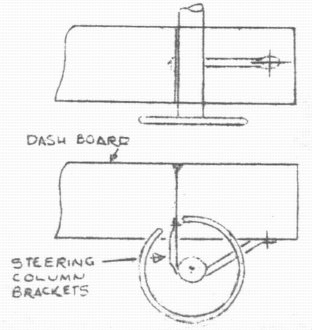 The steering rack is mounted on the
ready drilled mounting blocks. Place in position but leave 'U' bolts loose.
Place the column onto the rack and, with the steering wheel in position, adjust the wheel position to suit the individual
(if necessary enlarge pinion hole in floor). Tighten 'U' bolts and column clamp bolt. The column securing brackets
are mounted from the column to the dash valance. The short one on the left of the column mounted vertically and the long
one on the right, mounted horizontally.
The steering rack is mounted on the
ready drilled mounting blocks. Place in position but leave 'U' bolts loose.
Place the column onto the rack and, with the steering wheel in position, adjust the wheel position to suit the individual
(if necessary enlarge pinion hole in floor). Tighten 'U' bolts and column clamp bolt. The column securing brackets
are mounted from the column to the dash valance. The short one on the left of the column mounted vertically and the long
one on the right, mounted horizontally.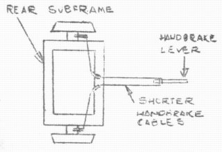 The right hand top flange on the sub-frame
must be bent down to ensure it does not foul the battery box. Offer the sub-frame up to the body and secure with 8 bolts
through the mounting blocks. Use 'penny' washers under the bolt heads on the inside of the car (Assembly Kit).
The right hand top flange on the sub-frame
must be bent down to ensure it does not foul the battery box. Offer the sub-frame up to the body and secure with 8 bolts
through the mounting blocks. Use 'penny' washers under the bolt heads on the inside of the car (Assembly Kit).
![]()


Last updated 28th November, 2023