 |
Pages: « 1, 2, 3, 4, 5, 6, 7, 8, 9, 10, 11, 12, 13, 14, 15, 16, 17, 18, 19, 20, 21 ... » : All |
   |
|
 Author Author |
 Right - join Part A to Part B etc, etc, etc (currently 14,506 views) Right - join Part A to Part B etc, etc, etc (currently 14,506 views) |
| Neil KilBane |
| Posted on: April 2nd, 2010, 09:13:03 |
  |
|
Maximum Member2


just a little fine tuning left to do.
Location: Newtown Forbes, Ireland
Posts: 1,420
Reputation: 0 (tot: ) |
|
| Don't forget you have to have a negative loom and a battery cable as well. |
|
|
|
|
 |
Reply: 15 - 599 |
|
 |
| Neil KilBane |
| Posted on: April 2nd, 2010, 09:33:03 |
|
|
Maximum Member2
just a little fine tuning left to do.
Location: Newtown Forbes, Ireland
Posts: 1,420
Reputation: 0 (tot: ) |
|
|
|
|
| |
Reply: 16 - 599 |
|
|
| Graham Bichard |
| Posted on: April 5th, 2010, 19:52:30 |
|
|
Maximum Member2

Posts: 751
|
|
Hi Neil - did you post that link in another thread? I've studied the pics on that SPi car in some depth!
I trust by a 'negative loom' you're refering to some sort of cable to take all the 'earths' back to the negative side of the battery? |
|
|
|
| |
Reply: 17 - 599 |
|
|
| Neil KilBane |
| Posted on: April 5th, 2010, 23:54:28 |
|
|
Maximum Member2
just a little fine tuning left to do.
Location: Newtown Forbes, Ireland
Posts: 1,420
Reputation: 0 (tot: ) |
|
| You need a few cables, the main negative feed goes to the engine then a feed for the rear loom and another for the front loom although you could take it from the engine. |
|
|
|
|
| |
Reply: 18 - 599 |
|
|
| Graham Bichard |
| Posted on: April 19th, 2010, 20:05:43 |
|
|
Maximum Member2
Posts: 751
|
|
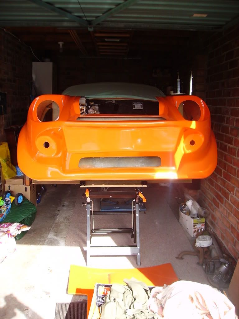
Right - I've just had a week at home so I was able to have a better look at my purchase! This is what I found:
I'm going to have to learn fibreglassing - these gouge's must've been done on the trailer when I brought it up from Shipley.
Passenger side:
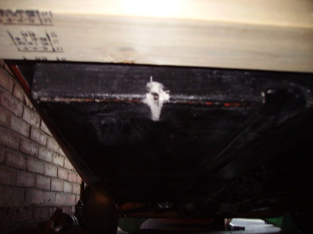
Drivers side:
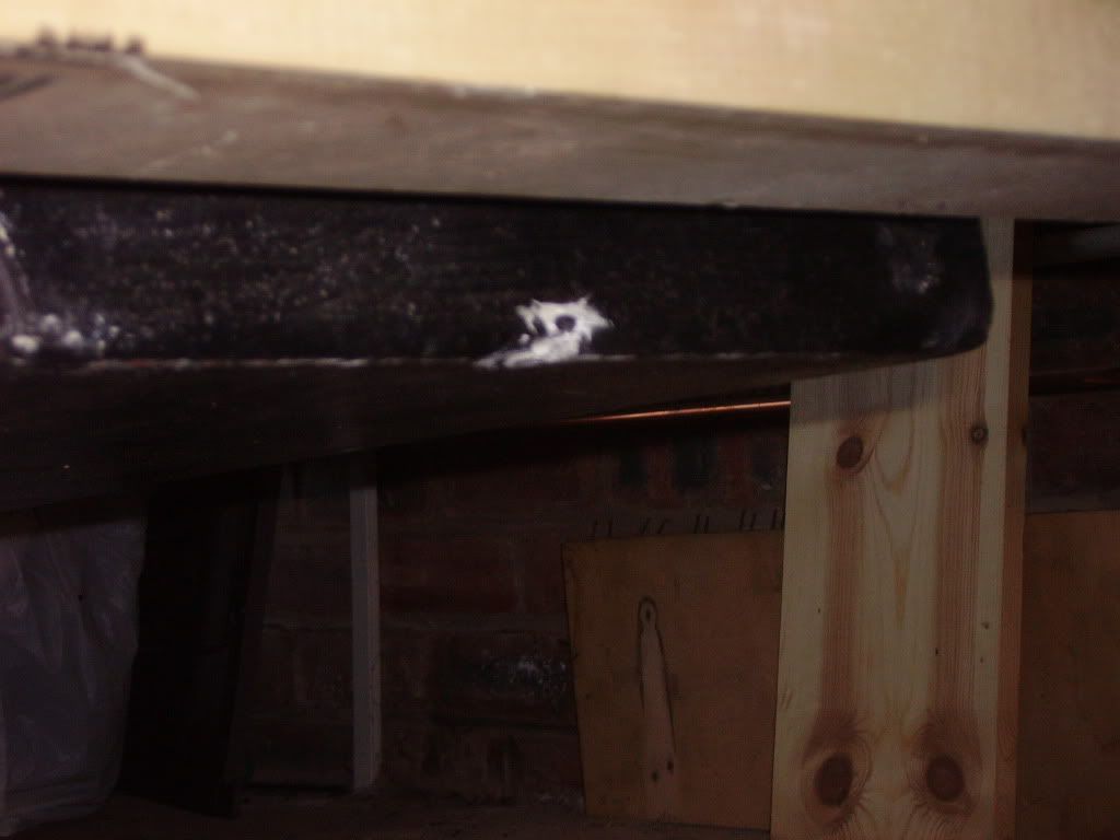
From the inside you can just see where the gouge has penetrated through to the inside (the drivers side isn't so bad):
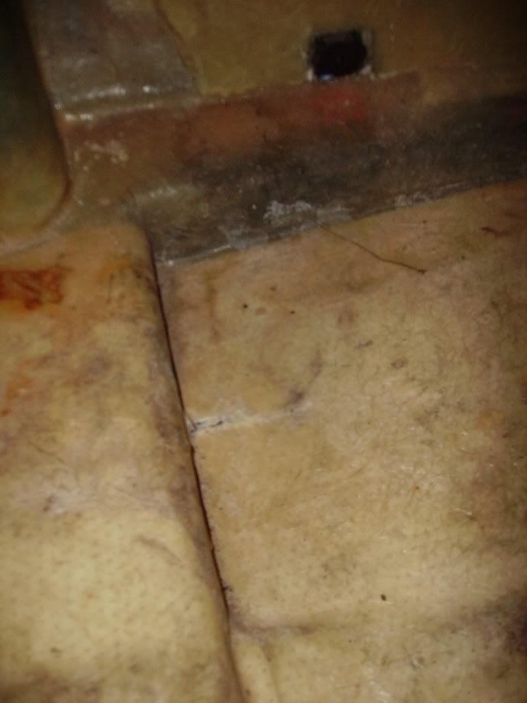
I take it the repair for this will be as per a hole (I'm referencing John's book here!)?
The bodywork isn't as good as the original photo's make it look - it's not a bad paint job, but there are a good number of scratches on it. I noticed this one when I picked it up:
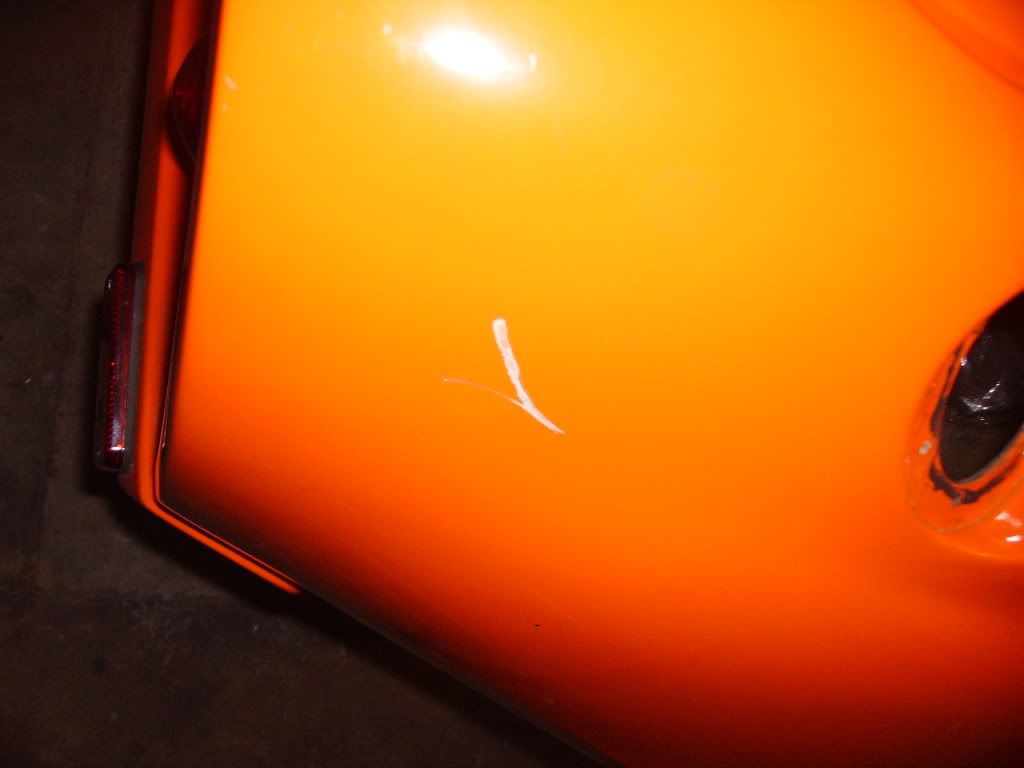
I also discovered another similar one on the NSR. Again refering to the 'Good Book', I take it this will require a repair to the gel coat?
I could be really annoyed about these (especially the floorpan damage  ) but to be honest I couldn't stop grinning whenever I opened the garage door! ) but to be honest I couldn't stop grinning whenever I opened the garage door!
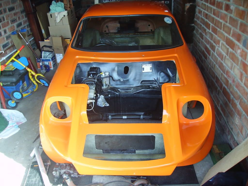
I did manage to clean the crap out of the interior, and take the existing loom out of the car and remove the carb/LCB and alternator. Just to give an idea of how it'll look I offered up the injection inlet manifold  : :
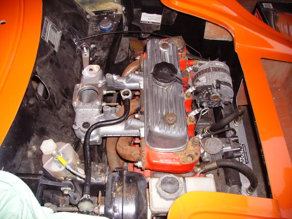
Looking at this picture, are the two holes (located just above the manifold, by the ratchet handle) for an ultimate engine steady? And whats the opinion about the loom hole - should I fill and move as I originally thought?
I had thought the next job would be to remove the front subframe and engine, but am now thinking fitting the injection body and engine looms might be a better plan, trying to get a neat layout prior to putting in the MPi engine with all the ancillaries. what do you think?
Oh, and the reason for getting only a little done on the car (apart from gutting the house ready for renovating, and digging/planting the allotment we've just been allocated)? I thought I'd better sort out my garage ready for working in (and thereby giving my mother her's back!):
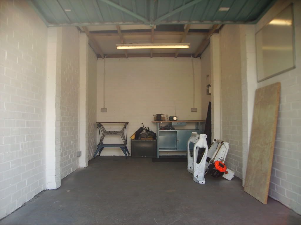
The kitchen work top I kept to do fibreglass work on (and doesn't the to-do board look empty ). |
|
|
|
| |
Reply: 19 - 599 |
|
|
| Peter Bremner |
| Posted on: April 19th, 2010, 23:09:54 |
|
|
Big Member


Location: Ongar, Essex
Posts: 410
|
|
Hello, just regard the gouges as drainage holes! Looks like we have another Tertius on the forum with a garage that clean. Just wait till you start grinding....
Yes, they're the holes for the engine steady. |
|
|
|
| |
Reply: 20 - 599 |
|
|
| Graham Bichard |
| Posted on: April 20th, 2010, 19:23:38 |
|
|
Maximum Member2
Posts: 751
|
|
Peter - having used the 'Search' button, I'll very much take that as a compliment having seen the standard of Tertius' work! Don't expect it to stay this clean though  . .
I've got a solid old set of chest of drawers to replace the workmate, and am still looking for some kitchen wall units to put on the rear wall for storage. And I'm getting an 18' lean-to shed built along side the garage to hold the garden stuff/bikes etc so hopefully it won't migrate into the garage. I'm planning to put some more florescent lights in the area of the workbench too, when the wall units are in.
Actually the picture makes the garage look bigger than it is - with a mini parked close to one wall I can strip and work on one wheel station. To do the other side I have to move the car over to the other side. Hardly ideal, but better than being outside!
I'll start looking for the best price for an engine steady now aswell then!
Drainage holes - pah! |
|
|
|
| |
Reply: 21 - 599 |
|
|
| Tertius van Zyl |
Posted on: April 21st, 2010, 10:32:06
 Attachment: imgp4252a.jpg - 21.56 KB (11828 views) Attachment: imgp4252a.jpg - 21.56 KB (11828 views) |
|
|
Big Member
Location: Johannesburg South Africa
Posts: 289
Reputation: -1 (tot: -1) |
|
Clean garage! You guys must be kidding! Thought I would check this morning in case the fairies have visited! Still getting the "You can't come into my house with that white mess under your shoes" from u know who!
Good luck Graham on your build. |
 |
|
|
|
| |
Reply: 22 - 599 |
|
|
| Joost van Dien |
| Posted on: May 26th, 2010, 08:14:13 |
|
|
Big Member

Drive it as much as possible!
Location: Kloosterzande, The Netherlands
Posts: 293
Reputation: 0 (tot: ) |
|
| Nice build! You don't see a new build very often! Good luck with it! |
|
|
|
 |
Reply: 23 - 599 |
|
|
| Graham Bichard |
| Posted on: June 8th, 2010, 19:24:31 |
|
|
Maximum Member2
Posts: 751
|
|
I was up home at the weekend, and managed to get an afternoon in the garage.
First a look at the new bits which had arrived - new radius arms with bits, new rear brake back plate assemblies and new drums:
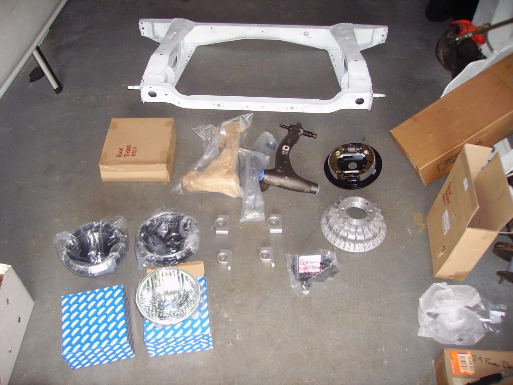
Also adjustable camber/castor rear brackets and some ally mounting brackets.
I got my 2.9 FD in the end - this should help with acceleration a bit (over the MPi's 2.7) and still be good for motorway work. I'll just have to make sure I build a nice torquey engine to pull it  : :
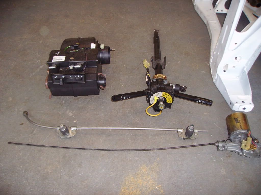
I took these bits up home while I was at it, having taken them apart/cleaned/rebuilt them:
And with the help of my nephews managed to get the engine/subframe out - is this a step forward or back :
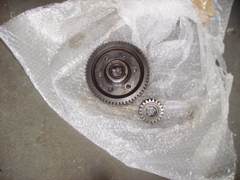
When I took the gear shift mech off I noticed this:
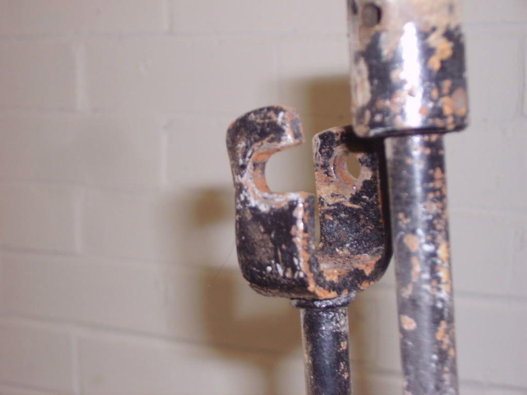
I take it the forks are meant to be parallel?
Final pic, as I've mentioned the car is going to have an MPi fitted. In an attempt to extract as much as I can from it, I spent a couple of evenings cleaning up one of the inlet manifolds I have, in an attempt to improve flow. Hopefully this picture will show just how rough the original casting is, and what I've managed to achieve to improve it:
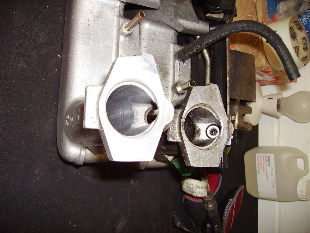
Ideally I'd get it chromed (to further aid flow and to reflect heat), but that costs money and might be a step too far  . .
The other thing I managed to do (it was a busy few days!) was visit East Coast Fibreglass Supplies and buy a few bits and pieces in order to let me do the repairs to the floorpan next time I'm up. Can't recommend them highly enough - very knowledgable and helpful. I'll certainly be putting my name down to attend their free fibreglassing courses when I'm able.
So - what do I do next (after the floor)? Should I put the loom in and look at possible fixing points? Do I leave it entering through the centre of the bulkhead? Or fuel pipes next? Any suggestions? |
|
|
|
| |
Reply: 24 - 599 |
|
|
| admin |
| Posted on: June 8th, 2010, 23:15:45 |
|
|
 Administrator Administrator


Location: Maidenhead, UK
Posts: 2,380
Reputation: 1 (tot: 1) |
|
Get the fuel line and front-to rear brake line in first (looks like you have done). Get the wipers and washers in while there's plenty of room to get to them. Fill in that hole in the bulkhead and take the loom through on the left. The wiring for the lights and indicators can go under the wings and into the dashboard area from each side.
Leave the wiring loom until you've got all the electrics on and have finalised the dashboard layout. The back section of the loom can go through the nearside sill and the double skin section behind the door. The front section you'll probably want to pull apart and lay out as required. Work out what relays you need and where you are going to mount them.
Fit up the heater and demisters before you do the dashboard so you don't end up with oil pressure pipes, choke cables, etc wanting to pass through the demister vents. You can then take the heater out to get to the bakc of the dashboard.
Consider fitting some heat sheilding material on the engine bulkhead behind where the manifold will go.
One thing is puzzling me - why hasn't the subframe got the bit of metal with the handbrake cable guide channels on it? |
Last modified June 8th, 2010, 23:20:44 by admin |
|
|
|
 |
Reply: 25 - 599 |
|
|
| Graham Bichard |
| Posted on: June 10th, 2010, 20:28:49 |
|
|
Maximum Member2
Posts: 751
|
|
Richard, I'm picking up some MPi fuel lines in the near future - hopefully they'll be pretty close (in length/fit), but even if they aren't I'll be able to use the connections for the fuel rail.
The shell has the (single) rear brake pipe fitted, which I'll have to revisit and resecure (IVA dictates clips no more than 12" apart for fuel & brake lines, I think).
I'll follow your advice regarding the wiper assembly, heater etc.
I'll have to have a look at the rear subframe on my mini to identify the handbrake brackets you're refering to  . .
Then the electrickery  |
|
|
|
| |
Reply: 26 - 599 |
|
|
| Graham Bichard |
| Posted on: June 19th, 2010, 21:01:12 |
|
|
Maximum Member2
Posts: 751
|
|
Been away last week, so I've spent this evening in the garage trying to keep my hands busy and do something constructive, so I've built up the inlet manifold:
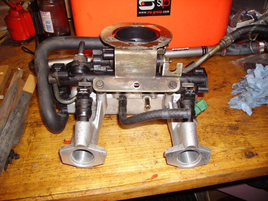
I'll be putting on the 52mm throttle body currently fitted to my mini, and the injectors will be cleaned or changed for larger ones, but thats another job done! |
|
|
|
| |
Reply: 27 - 599 |
|
|
| Graham Bichard |
| Posted on: October 12th, 2010, 17:50:13 |
|
|
Maximum Member2
Posts: 751
|
|
Well, having seen Lee's car on the road, I thought I'd better put in an update to show I am doing something
Got some more bits through the post a little while ago:
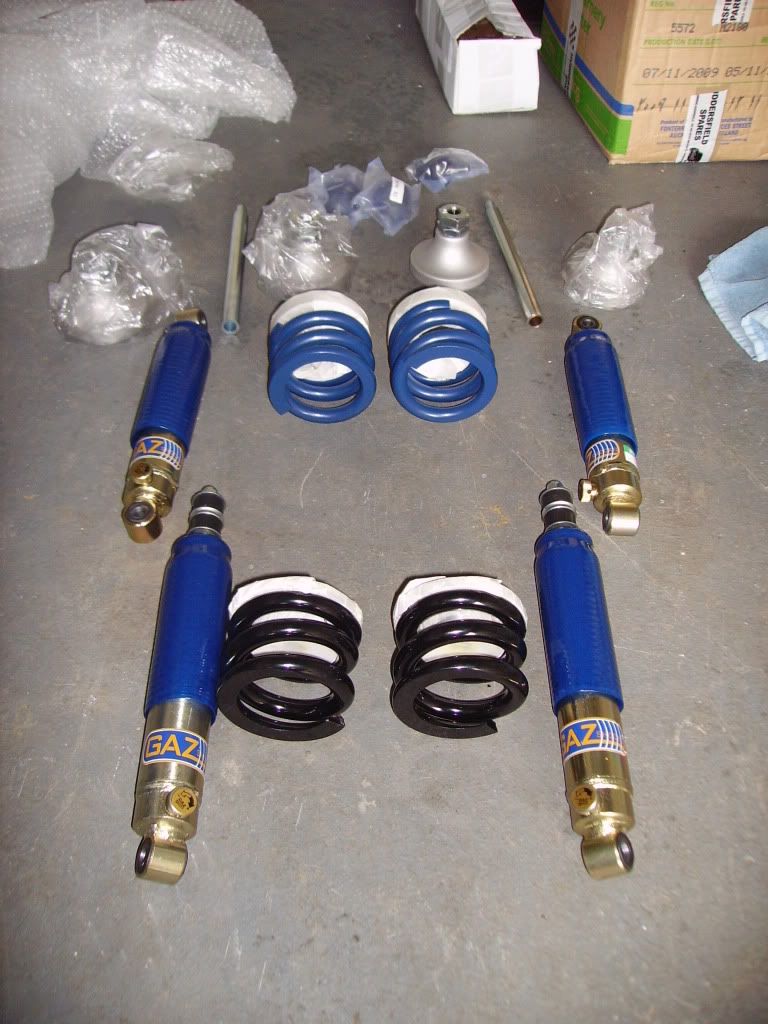
The springs for the front are stiffer than those for the rear (as per last winters mag, I think). I'll see how this handles - if it proves a bit soft it should be quite easy to change for harder springs, or perhaps fit a rear anti-roll bar. I've heard good things about the Gaz shocks too. These are standard height items - I'm not going for the lowered look. There a lot of 'cliff-face' speed ramps down my street. I don't want to pull the exhaust off every time I go over them! I have started to build up the front subframe with these but one of the plastic cups hasn't seated properly (I might be getting a bit of hydrostatic lock effect from being a bit generous with the grease!) so I'll have to strip it down again, when I get my garage back!
I now know what was meant about grinding the GRP and all the white dust! And I was only doing a very small area! It took me a while to find a cheapish workbench which had a reasonable weight capacity but eventually got the shell raised:
Once safely up, I was able to prepare the edges of the trailor damaged holes. The drivers side wasn't too bad so was repaired from underneath:
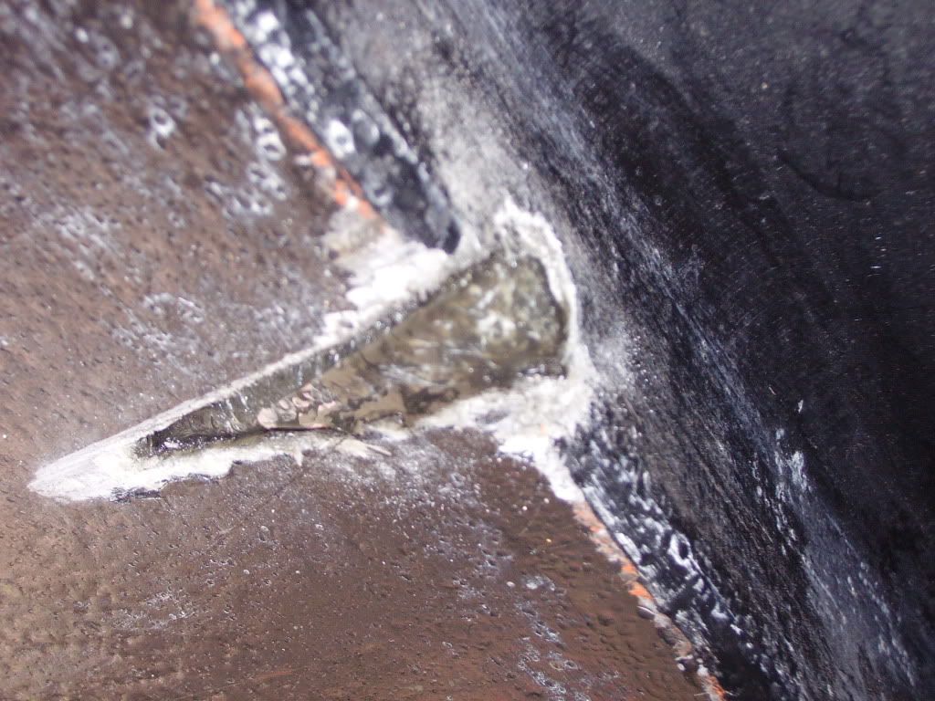
(This is before the repair)
The passenger side had gone through to the interior so I cut through and chamfered the edges prior to repairing from inside the car (no point in working against gravity!):
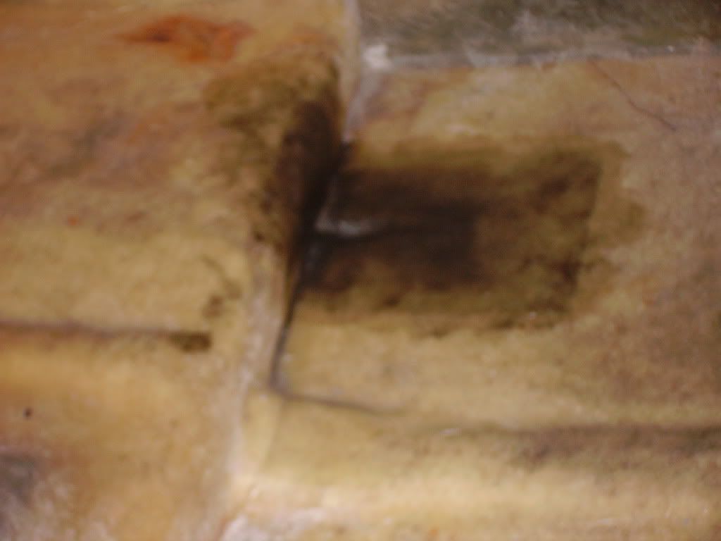
(This is mid repair)
You'll notice I haven't mentioned the loom hole in the bulkhead. I thought I'd work out the best route for the electrics first. Who knows - I don't intend to use that hole but........ I can always fill it in later.
I also cleaned up the fuel lines:
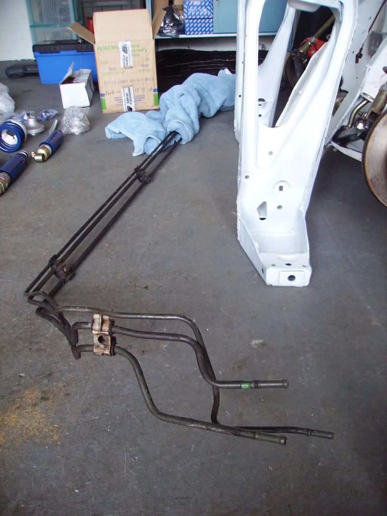
I was hoping to get these fitted this weekend, but after having a look at the shell and considering things over a cup of tea, I haven't got around to it yet. I need to reposition the shell (safely) on the wood/workbenches in order to allow me to offer up the solid pipes prior to drilling holes and securing them. I will have to cut the pipes at the rear because of the different shape of the MM to a mini shell. (Lee (anyone?) did you use flexible pipe to join the fuel lines together? Who supplied it, and any problems with IVA on this?). I also need to find out how these pipes are secured to the shell - by this I mean, when viewed from underneath the retaining clips have a plastic, cross-headed screw head but I don't know what fits into the top of these (from inside the shell). I can't see a screw thread in the plastic, but that would seem the obvious solution (if so, what is the thread?). I did pull up the carpet quickly on the mpi but couldn't see the answer (too much tape in the way!).
I also need to come up with a solution to problem of fuelling the thing. I found on the net a guy who has adapted a van tank to accept the mpi pump internally (horizontally mounted), but I'm not sure I want to cut up the new tank I've now got my hands on. I realise a return will have to be put in, also a breather at the highest point (for the carbon canister) but there must be a relatively simple solution using an external in line fuel pump and filter. Any ideas anyone, of a fuel system (Garry, Wil - any experience from the forced induction world? They must need 3bar-ish of pressure to fuel them?)
So much for getting the shell out of my mothers garage - mine is bursting with boxes (extension still not built). This could take some time..........
But I did get something put on - the wiper spindles:
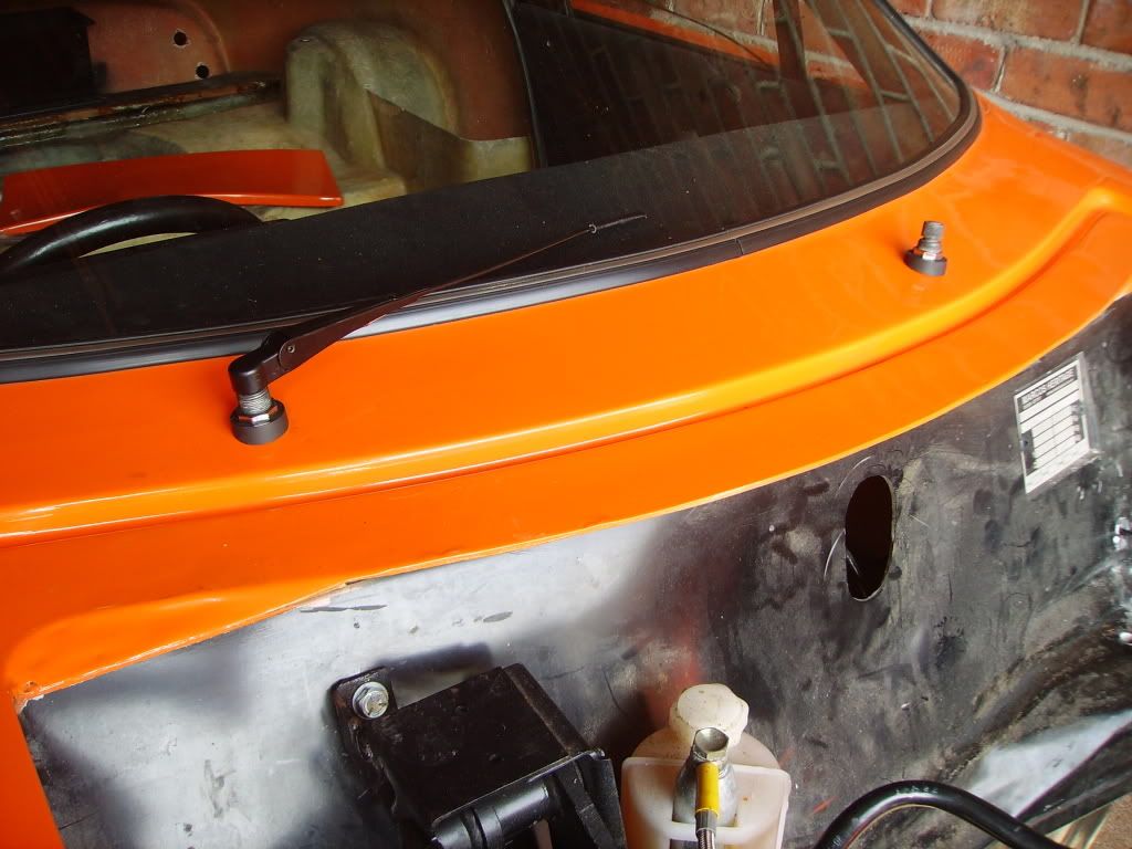
Building at last |
|
|
|
| |
Reply: 28 - 599 |
|
|
| Neil KilBane |
| Posted on: October 12th, 2010, 20:12:02 |
|
|
Maximum Member2
just a little fine tuning left to do.
Location: Newtown Forbes, Ireland
Posts: 1,420
Reputation: 0 (tot: ) |
|
Nice bit of progress there.
Will be interesting to see how the coil springs work out.
Your wiper spindles look very flat to the body work, mine are more parallel to the windscreen. |
|
|
|
|
| |
Reply: 29 - 599 |
|
|
Pages: « 1, 2, 3, 4, 5, 6, 7, 8, 9, 10, 11, 12, 13, 14, 15, 16, 17, 18, 19, 20, 21 ... » : All |
|
|
| |
| Forum Rules |
You may not post new threads
You may not post replies
You may not post polls
You may not post attachments
|
HTML is on
Blah Code is on
Smilies are on
|
|
|
|


 Mini Marcos Forum > General Boards > Mini Marcos > Right - join Part A to Part B etc, etc, etc
 Logged